
The five most common mistakes we make when modeling a ship surface.
- Alexander Alexanov
- Apr 29, 2020
- 6 min read

I think I’m not very mistaken if I say that 95% of the programs for modeling and smoothing the hull surface use NURBS mathematics. If 20 years ago, the result was a just body lines drawing, given in the form of lines and used mainly for hydrostatics calculations, now the resulting surface is transferred to many different calculation and modeling programs. It is important to remember that the surface is transmitted with mathematical precision, without changing shape.
In summary, the model you created will be used in many different calculation programs and geometry modeling systems. The result of all these programs will directly depend on the quality of the incoming surface model. The surface model for most of these programs is used as is, without additional checks. Therefore, all the problems and pitfalls that arise when modeling the surface can not be detected immediately. All this imposes additional responsibility on the designer, engaged in modeling the surface of the hull.
For many years I have been doing the final smoothing of ship hull surfaces in Shape Maker. As initial information for smoothing, it is often necessary to use preliminary surface models made in other systems, sometimes even not at all adapted for modeling a ship's surface. And, every time, I see the same repeating mistakes made during the modeling. I hope that this article will at least partially avoid these errors in the future or allow users to more consciously choose a tool for smoothing the hull.
Partitioning the surface into patches.
Before you begin modeling the surface, plan how your surface will be divided into separate surface patches. Rational division into patches allows you to achieve better quality of the smoothed surface and minimal labor. With an ill-conceived partition of the surface, the number of patches and, accordingly, the complexity of the work grows like a snowball. Sometimes, on models, one can see the designer’s panic and despair, which closes one hole of the surface by another, and thereby creates even more problems for itself, and the deadline for work is inexorably approaching.

An example of unsuccessful splitting into surface patches. It is very difficult to achieve smooth mating of surface patches. The bow and stern borders of the surface are located close to each other. This does not allow to achieve the required smoothness.
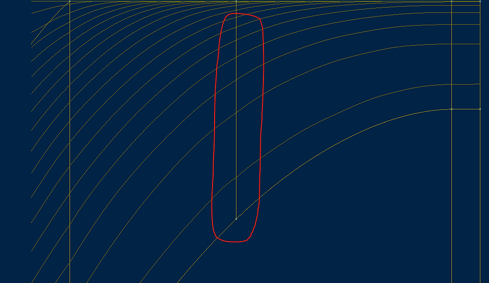
The problem of joining two surface patches along a common border. It is very important to correctly set the shape of a common boundary curve.

An example of an unsuccessful splitting of a aft ship. Waterlines are compressed along the longitudinal axis. As I understand it, the initial idea was to build a smooth aft surface.

An example of a failed common point for three surface patches. Cross sections knuckles are visible. In order to avoid local non smoothness of surfaces, it is necessary that all boundary lines at this point belong to the same plane.

Problems of smoothing surfaces consisting of a large number of patches. In addition to smoothing the actual surface patches, it is necessary to perform smooth connection with adjacent patches. If the boundary lines are not defined exactly, this can create a problem for the entire surface. I prefer to avoid dividing into patches of the surface where possible and to modeling curved surfaces in one section. This gives a better and smoother surface.

Difficulties in controlling surface shape in an area close to a flat side. Such a division of the surface into patches gives practically no chance of building a smooth surface in this area. This can be seen by the shape of the sections on the flat side.
Incorrect or uncontrolled parameterization of surface areas.
Features of NURBS surfaces are that triangular or quadrangular sections of surfaces are typically used. The surface is represented by lines of an equal parameter in two directions in the parameter space. The correct distribution of parametric curves and, correspondingly, control points of the surface, is very important for the correct smoothing of surfaces.In some cases, it is simply not possible to get the correct result. Therefore, the correct division into surface sections is the path to successful smoothing.
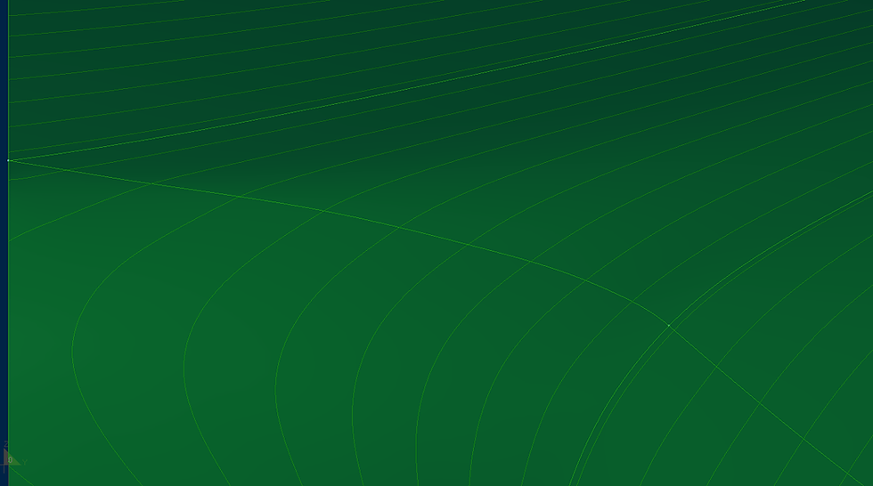
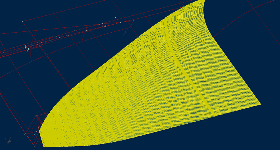
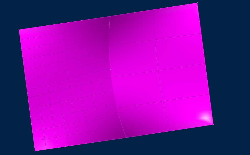
Uneven parameterization of the surface leads to difficulties in smoothing the surface.

An example of successful and unsuccessful parametrization of surfaces defined on the same boundary lines.The left part of the surface is a cylindrical surface. The right part of the surface is more likely to resemble the shape of a sail, and no modification of the control points of this surface makes it possible to make it cylindrical.Another practical example of incorrect parameterization of a surface area was previously described here.
The allocation of flat areas of the side and bottom and ruled surfaces in separate surface patches.
Of course, it is much easier to describe the entire surface of the hull as one large surface area.But the disadvantages of such a model outweigh its advantages.The flat side and flat bottom lines well control the shape of the surface and ignoring them leads to the following results:

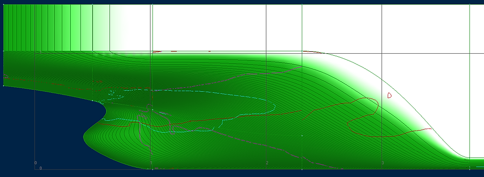
View from above.The flat bottom is not allocated in a separate area.The image of the waterlines is compressed in length.

View of the flat board.The image is compressed in length.The shape of the line of the flat side is clearly not what the designer would like to see.
Hull smoothing errors are probably due to luck of surface quality control tools.

Waterlines in the stern. The image is compressed along the longitudinal axis.

Waterlines in the aft gondola area. The image is compressed along the longitudinal axis. It can be seen that the boundary line of the two patches of the surface is too wide in the area of the flat bottom or the aft patch of the surface should be more rounded.
Incorrect line shape of the boundaries of two surface patches. Knuckles visible on frames at the connection between patches.
The distribution of inflection lines on the surface shows undesirable inflections occurring on the orthogonal sections of the body and insufficiently smooth joining of the surface area.
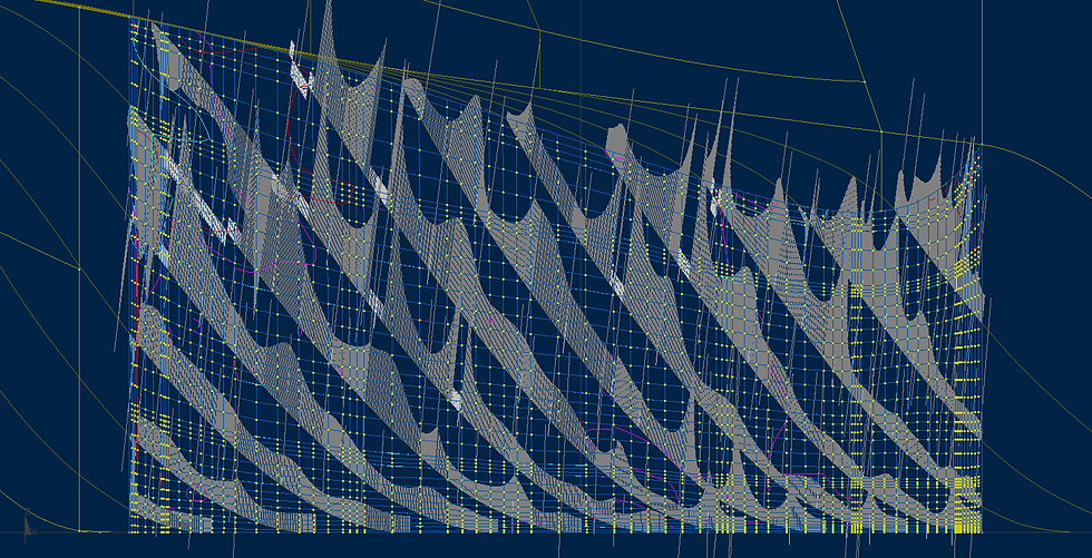
Excessive number of surface patches control points.
The is not shaded surface shown above. It just surface patch control points are visualized. I don’t know what was driven by the author of this model, perhaps just a lack of understanding of the mathematical nature of NURBS surfaces or the program that was used for modeling. Visually, the surface turned out to be smooth, but it is very difficult to use it later for calculations or modeling. Starting with the fact that even visualizing such a surface (350x350 control points) is time-consuming, not to mention other, more complex calculations. For example, it takes more than one hour to calculate the shell plate folding on this surface.
Holes between surface patches.

This is the most common problem. Holes form if the geometry of the boundaries of adjacent surface patches does not coincide. In any case, holes can only be avoided if the boundary curves are geometrically identical. In all other cases, the holes can only be reduced, but not completely avoided. Any methods of approximating boundary curves to each other, such as interpolation or approximation, increase the number of control points and, accordingly, the number of control points on adjacent surfaces. This, in turn, increases the complexity of changing the shape of surface sections.
Holes between surface patches are one of the biggest problems when transferring a surface model to other systems. Holes create problems for many design programs and programs for modeling hull structures. Moreover, not all of these programs determine the allowable gaps between surfaces at the import stage. Often problems caused by cracks occur later. For example, in CFD calculations, a vessel sinks as water enters through open holes in the hull surface model. Obtaining incorrect geometry of hull parts and reamers of the shell plates in this case is most dangerous, since it can only be detected at the production stage. Correction of these errors will require additional financial and time costs during the construction of the building.
I also note that some of the hull modeling systems are extremely demanding on the gaps between the surfaces, so Aveva checks the gaps with an accuracy of microns.
As I said above, the absence of gaps is guaranteed only by geometrically identical boundaries of adjacent sections, but it is possible to have a different number of control points on such curves. This avoids gaps between surface areas and, at the same time, has a different number of control points. Thus, simple sections will have fewer points, and complex sections will have more, but no gaps at common borders.

Some surface modeling programs do this automatically. Check for such a feature in the program you are using.Even more possibilities appear if the program supports T-connection.
The T-connection allows you to join on the same border a different number of surface areas from different sides.In this case, gaps between the surfaces do not occur.
The model of the hull surface is one of the most important components of the project as a whole, with which many different departments work. The result of the work of a large team can directly depend on how well the surface smoothing work is done. Of course, nothing is perfect and in each surface you can find certain errors.The goeal of the designer is to try to minimize them to obtain a better result.


Comments