
Another argument in favor of the correct hull form patching.
- Alexander Alexanov
- Nov 6, 2019
- 2 min read
Updated: Feb 23, 2020
Very often I encounter the surface of hulls from one patch. Of course, this greatly simplifies the modeling process. But, as I wrote earlier here - "How to split surface for patches right way.", this modeling method is absolutely not suitable for the final smoothing of the surface. When using only one surface patch, it is impossible to clearly distinguish the areas of a flat side and a flat bottom. The shape of a curved surface area adjacent to flat areas in this case is almost impossible to control.
I will give an example:
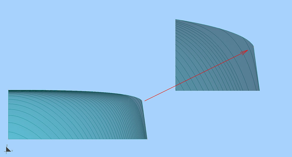
Recently, I was modeling the surface of the hull and superstructure of a very large vessel. Unfortunately, I cannot show the entire hull of the ship here. I will give only an example of a surface area with which I had problems. This is a fairly simple patch of the superstructure. The patch is formed by the line of the maximum deck width of the bow, the profile of the buttock in CL, the contour line of the upper part of the superstructure and, in the stern, the contour line of the flat side. Note that the line of maximum deck width has a straight area on which the flat side of the ship rests. At first glance, such a plot does not have a big problem for modeling.
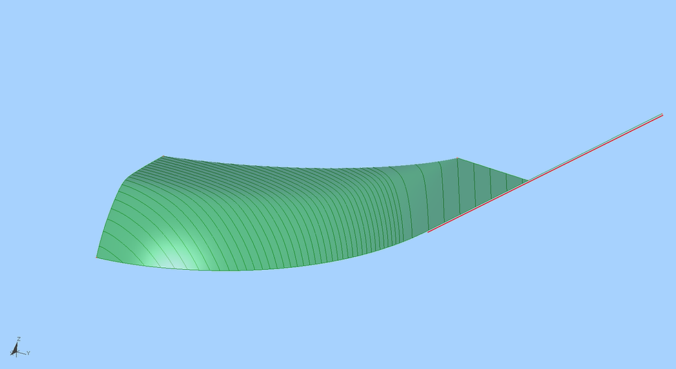
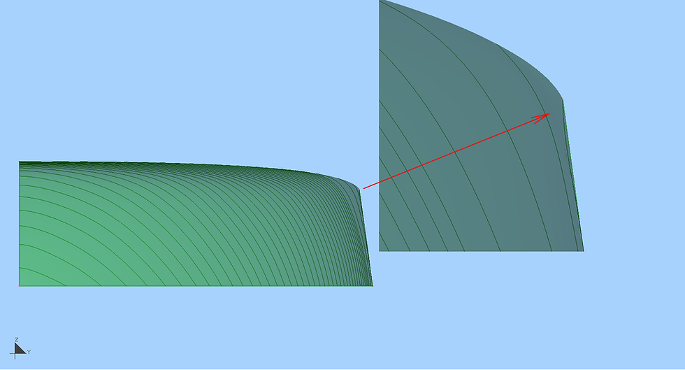
But, for this patch there is only one limitation. The inclined line of the side contour and the flat part of the deck lines should form a plane in the aft part of our patch. It would seem that it is enough to build a plane bounded by these two lines and set the control points of the surface in this area strictly on this plane and the problem will be solved. But as I did not try, frame sections of the surface in the vicinity of the side contour line looked unacceptable.
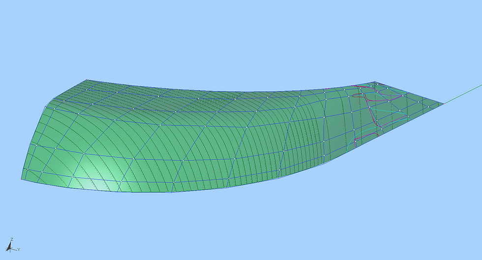
Manipulations with control points of the surface did not make any significant changes in the shape of the upper line of our section in the form of frames. The rows of surface control points fan out and twist the surface.
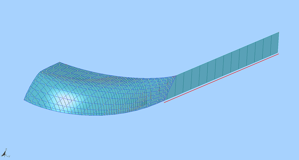
After some thought, I realized that in this case it is necessary to separate the flat part of this surface into two separate patches. To do this, I built a new boundary line, passing from the aft point of the top line of our surface to the end point of a flat deck line area. Now our surface area is completely curved and mates with a flat side of the board. This solution made it possible to smooth out this surface area very quickly. Now the distribution of control points of the surface looks natural, and the line of the flat side is set exactly.


Comments