
Five stages of fore body smoothing by one surface patch.
- Alexander Alexanov
- Apr 26, 2021
- 10 min read
Updated: Jun 5, 2021

As I have said many times, in Shape Maker, as well as in many other programs, the surface of a hull can be modeled in a variety of ways. If the surface is rather complex, for example, a fore ship with a bulbous bow, such a solution is often encountered - the curved section of the surface is divided into three parts: - the main surface from the midsection of the frame and before the beginning of the bulb is separated from the bow sections by the frame line, - the surface of the bulb, - the surface is above the bulb. The main section can be drawn from a set of frames, bow portions of surfaces from a set of waterlines. If you need to quickly build the surface of the enclosure for calculations at the initial stage, this solution may be optimal.

When it comes to more accurate surface modeling, this method is doomed to fail. No matter how hard the designer tries, in the area of junction of the surface sections, defects in the curvature of lines and surfaces will be visually noticeable. In any case, the joining of the surface sections gives only the smoothness of the first derivative of the curve. The curvature at the joint has a gap.

Therefore, I prefer to use one surface patch to model the bow surface. This method has been proven by many years of modeling practice and is excellent both at the initial stage of the project and for the final smoothing of the hull. The essence of this method is a sequential increase in the number of control points of the surface when approaching the prototype. At the initial stage of modeling, a minimum number of control points are used. In this case, it is very important not only to try to get closer to the required shape, but also to correctly position the control points of the surface.

Since all control points of a surface have the same weight, it is very important to place them evenly over the entire surface. When I work with a surface, I try to arrange the rows of control points as streamlines around the modeled surface. The grid of surface control points should look smooth, then the surface itself will be smoother. Since the surface patch rests on the boundary curves, it is very important to correctly position the control polygon of the boundary curve at the initial stage. The unevenly spaced control points of a boundary curve will eventually give an uneven distribution of the control points of the surface that rests on that curve. In Shape Maker, increasing the number of surface control points is achieved by increasing the points on the boundary curves. In this case, the shape of the surface does not change. Thus, the shape, which was achieved with a minimum set of control points, will not change. All that remains is to change those areas of the surface that cannot be modeled with fewer control points. This simplifies and speeds up the modeling process.
In general, modeling surfaces with a sufficiently large set of control points with the same weights has many advantages:
- Due to the locality property of changing the shape of a surface area, most of it remains unchanged when the position of one control point is changed. This allows better control of the shape of the entire surface during local changes. The designer can be sure that only the part that needs to be changed is changed.
- Modeling a surface with a large number of control points makes the surface smoother and more predictable. - The ability to locally control the shape of the surface allows for better control of the curvature of the surface. In this case, it is enough just to change the position of the control point by 1mm or even by 0.1mm on the scale of the ship's hull. Of course, such a change in the position of the control point is not possible on the display screen, but for this, Shape Maker has a special option to scale the cursor movement.
- The even and smooth distribution of the grid of surface control points makes the surface itself smoother.

Some of the novice Shape Maker users, looking at a 35x35 grid of control points, wonder how it is possible to build a correct grid of 1225 points in the foreseeable future. Sequential increase in surface control points provides significant time savings in modeling. In addition to this, Shape Maker has a large set of functions that allow you to reposition the area of surface control points, straighten and smooth the surface area and rows of control points. It is also possible to change the surface area by moving one point on the surface. The combination of all of these techniques, together with large-scale cursor movement, makes it possible to reshape surfaces consistently, locally, and predictably.
Consider the sequence of stages of surface formation.
1.Preparation of initial data.
Two-dimensional and three-dimensional section lines can be used as initial data. Lines are loaded from DXF files. Also prototype surfaces imported from IGES files can be used. It is very important that lines and surfaces have a coordinate system origin that matches the ship's coordinate system. I will not dwell on this in detail, since this process has already been described earlier here. I will only note that in most cases the approximation to the initial data is controlled by the coincidence of the sections of the prototype and the modeled surface. Therefore, the grid of the project must be set in accordance with the grid of the prototype.

2. Initial setting of boundary lines and the surface area itself.
The classic shape of the curved patch of the surface of the ship’s bow consists of four boundary lines: - bilge radius line, - flat bottom line, - stem line, - the line of the flat side, passing into the line of the boulevard. These four lines form a patch of the ship’s fore surface and allow you to define a surface with an optimal grid distribution for the control polygon. Boundary lines are straight when initially specified. When editing such a straight line, a control polygon of two intermediate points appears, by controlling which you can change the shape of the curve. As in the case of a surface, adding control points on the boundary curve does not change its shape. Increasing the control points gives you more room to accurately describe the curve. It should be remembered that increasing the control points of the boundary curve leads to an increase in the control points of the surface. When the shape of the boundary curve changes, the surface area will change naturally. You can select the mode of changing both the entire area of the surface and the specified area of the surface.

The created surface area has a minimum set of control points. At this stage, it is important to determine the correct location of the rows of control points of our surface. Vertical rows closer to the bilge line should be located in the planes of the frames. This will make it easier to control their shape. The rows of the point nearest to the stem should follow its shape. In the longitudinal direction, the rows of control points should be located as imaginary streamlines around our surface. In the future, control points will be added between the existing rows. The distribution structure of the surface control points will generally remain unchanged.

At this stage, it is important to set the correct control points closest to the boundary lines and responsible for the tangent surfaces at the boundaries. So, if we want to have a smooth conjugation of the surface with the mid-frame, we need to set horizontally the points closest to the cheekbone radius line. We will do the same with the line of the flat side and flat bottom. To do this, Shape Maker has hot keys - so if you click on mouse with pressed Ctrl on the line between the boundary point and the nearest control point of the surface, this line will become vertical or horizontal on the current projection.
3. Approaching the prototype lines.
I hasten to disappoint those who look at the world through rose-colored glasses. We must finally admit that the world, alas, is imperfect. The prototype used to build our surface is also imperfect. Therefore, only the designer can decide how closely to approach the prototype. The process of getting closer to the prototype is to move the control points of our surface. As you have already noticed, if the visualization of the surface sections is turned on, the sections change their shape simultaneously with the change in the position of the points of the control polygon. The fitting process is reduced to the approximation of the shape of the sections of our surface to the sections of the prototype. For the convenience of visual comparison of cross-sections, it is recommended to use a different color for the cross-sections of the prototype surface and the designed surface. Simultaneously with the approach to the cross-sections of the prototype, it should be remembered that the control points of the surface are evenly distributed.


There are a few simple rules for fitting surfaces:
- Do not try to achieve the final result by changing the position of just one point on the surface. As a rule, it is necessary to change the position of several adjacent points.
- If you cannot achieve the desired result with the existing set of control points, do not rush to increase their number. Check the rest of the surface. Perhaps you can still improve the surface shape of these areas. The rapid increase in the set of control points increases the laboriousness of the fitting.
- For a more precise fit, use a scaled cursor movement.
- After enlarging the control points, first refine the shape of the surface boundary lines.
- If there are a significant number of control points, use the movement of the group of points. This will greatly facilitate the fitting process.
4. Determination of the shape of the surface.
After the designed surface is close to the prototype, the moment of truth comes. Finally, we need to more accurately define what the surface will actually look like. At this stage, the designer must decide where the bend areas of the surface cross-sections will be located. To do this, Shape Maker has the ability to visualize inflection lines. In short, these are lines on the surface that show us the areas of change in the direction of the curvature of the sections.

When using surfaces of the third degree for modeling, the inflection lines cannot be completely smooth. This is fine, but to get a smoother surface, you should try to make the inflection lines as smooth as possible. The visualization of the inflection lines also allows the detection of bumps in the surface, which are often invisible to the eye. In short, the correct location of the surface bend lines gives us a guarantee that there are no unwanted kinks and bumps on the surface. Like surface sections, inflection lines change their shape when the position of the control points changes. At this stage, it is better to use a scaled cursor movement with a 1mm scale. This will allow us to change the position of the inflection line without deviating far from the initial surface, which we brought closer to the prototype. The visualization of inflection lines is a very accurate and convenient tool that allows you to quickly identify all surface defects. At this stage, it is very convenient to use the function of automatic smoothing of control point areas.
5. Smoothing the surface of the hull.
We approached the stage of final smoothing of the surface with the following results:
- The shape of the boundary lines is finally determined,
- The number of points to control the polygon surface 35x35,
- The surface is close to the prototype,
- The inflection lines are correctly positioned on the surface.

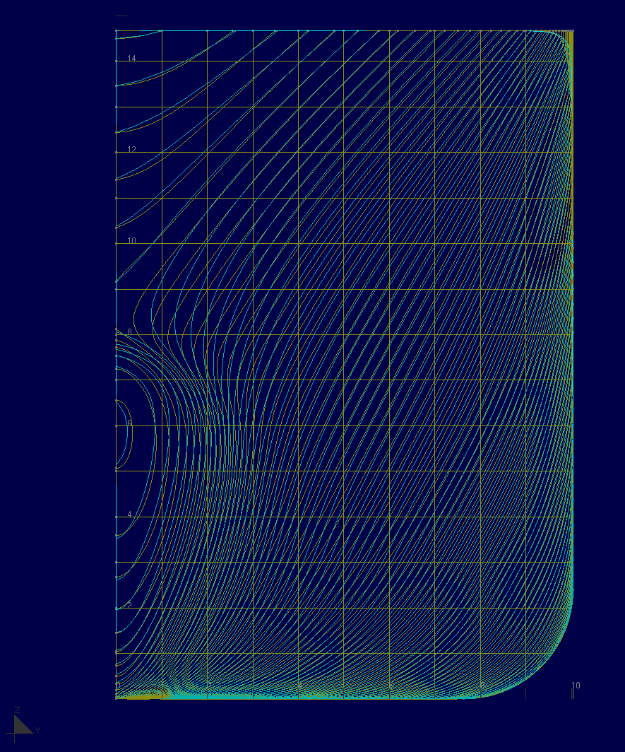
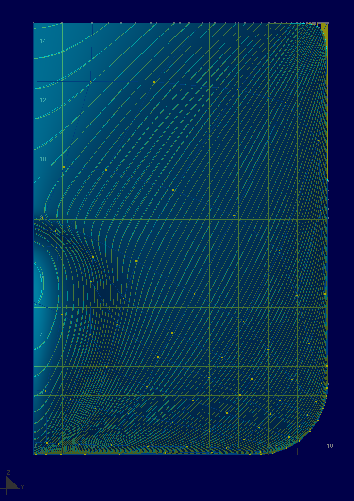
Even if all these conditions are met, the sections of our surface can have local flattening. To visualize the quality of the section’s shape, graphs of curvature radii are used. The larger the radius of curvature, the longer the line corresponding to it. Ideally, the graph of the radii of curvature should be a smooth line that does not contain peaks. Radius of curvature plots are displayed along with surface sections and automatically update when the position of control points changes. At this stage, only scaled movement of the cursor with a scale value of 1mm or less is used. Manual smoothing is a change in the position of the nearest control point or directly a point on the surface in order to smooth the peak of curvature. Curvature plots of sections give a complete picture of the shape of the surface. During the smoothing process, you can also use the automatic methods of smoothing the control point area and moving the control point area. In this case, one should remember about the correct location of the surface inflection lines. Smoothing at this stage is a very precise process that does not significantly change the surface, but only improves it locally. In any case, the decision on the admissibility of the surface smoothness remains with the designer. While visualizing the radii of curvature gives a good idea of the shape of surfaces, in some areas it is difficult to control the curvature. For example, in the case of cross-section frames near the mid-ship frame. The sections are close together and the curvature plots are a mess of lines. In this case, it is convenient to work in isometric views.
For true perfectionists, there is another way to control the shape of the surface - this is the visualization of lines of equal angles of inclination of the surface. In fact, it is analogous to zebra rendering. Often, even a well-smoothed surface in this mode does not look very good. For smoothing in this mode, I recommend setting the division value when moving the cursor scaled to 0.1mm, turn off the visualization of lines between control points and turn on the option to move the cursor perpendicular to the work plane. After some practice, I find this method even more convenient than curvature smoothing. Especially if you use automatic fairing method, based on surface area minimization. As a result, the surface smoothness can be obtained close to the quality of automobile surfaces. There is a lot of debate about the need for such surface accuracy, but I think that for smoothing super yachts and large cruise ships, such quality would not hurt.

Hull shape is a visual art object, and it is good to have possibility for make it as you want, but not like your software can.


Very useful information & long awaited. You are continuously raising standards.