Learn the Shape Maker. Initial data preparation.
- Alexander Alexanov
- Dec 1, 2020
- 2 min read
Updated: Dec 3, 2020

Any project of any type of ship at the earliest stage of development must ultimately have a lines drawing of the ship's hull. Of course, any project is based on previous experience and your new project will be similar to any prototype. I would not like to dwell in this article on how to select the most suitable prototype, as well as all other parameters of the future ship. The designer knows this like no one else and it is on his technical solutions that the project is built. As a rule, at the stage of developing a lines drawing, all the main technical solutions have already been taken. At least the main dimensions, the mid ship bilge radius, the shape of the stems, the contours of the decks and the design waterline, and the displacement should already be known.
The most important information for designing a ship's hull surface is provided in the General Arrangement drawing. The profile of the ship, the contour of the mid ship frame, the decks, as a rule, presented in this drawing are the initial information for the design of the surface. Often, the General Arrangement drawing shows the position of the flat side and flat bottom line.
The General Arrangement drawing can be loaded into Shape Maker. To do this, you need to do the following:
- save the required views in separate DXF files,
- align the origin of the drawing coordinate system with the origin of the AutoCAD coordinate system,
- clean up unnecessary information that is not needed for surface design, such as texts, hatches, clouds, etc.
- explode blocks,
- save the DXF file as early as possible, preferably R12. In this case, all drawing elements are converted to the most primitive ones, which are loaded into Shape Maker without distortion. Note that the current version of DXF import does not support ellipses.

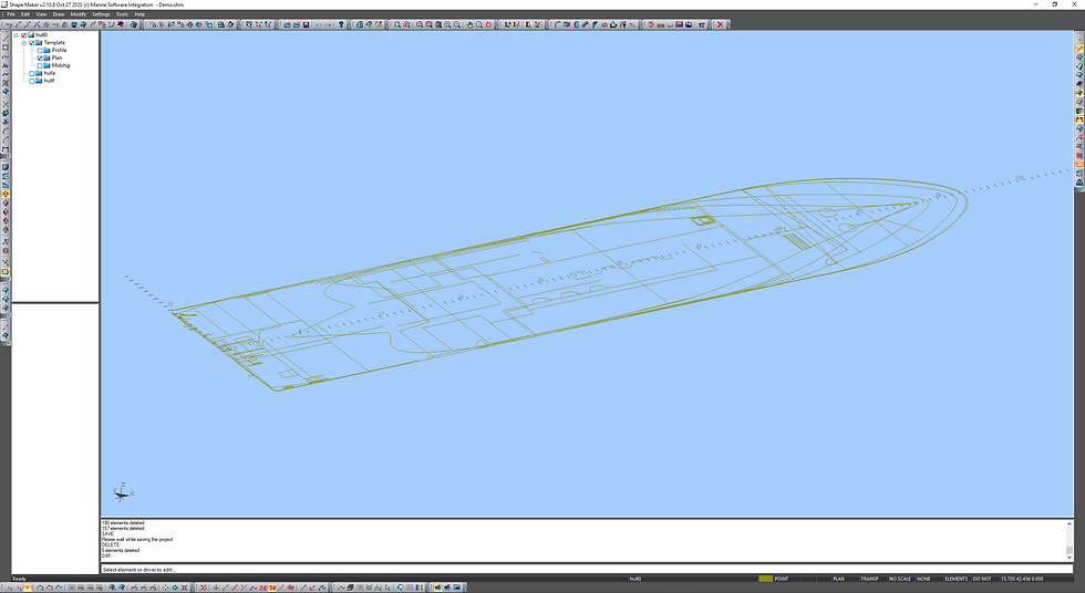
To import views into Shape Maker, it is best to create a structure from the following blocks and import each view into a corresponding block. This makes it easier to import and visualize information. Any of the blocks can be turned on or off at any time.
Template
- Profile
- Plan
- Midship

The import process is as follows:
- the current block is selected, for example Profile
- the corresponding DXF file is imported into the current block.

All views from the general arrangement drawing are presented on the XY plane and, accordingly, on the same plane will be imported into Shape Maker. To position them in the appropriate planes, you can use the rotation and movement of the blocks. Use the block selection by block element for transformation.


Now that all the views are loaded into Shape Maker, we need to define a grid of frames, waterlines and buttocks. Shape Maker allows you to define areas with constant spacing in all three coordinates. Additional sections are highlighted in yellow during output. Stations, structural waterline, and decks can be specified as additional sections. The grid can be changed at any time. Surface sections are visualized in accordance with the section planes defined by the grid. At this point, the preliminary preparation process can be considered complete.


Mr ALEXANDER
thankyou for all your efforts to success these postes
but try to help us to get all tutorials lessons i pdf formate to dowwload them
regards