
Ship's hydrodynamics with Shape Maker.
- Alexander Alexanov
- Apr 9, 2019
- 5 min read
Updated: May 23, 2021
The shape of the hull is extremely subjective. Anyway, we evaluate it in terms of likes-dislikes or pretty-not pretty. Of course, in the actual design process, a much larger number of parameters are estimated that affect the behaviour of the vessel at sea. One of them, which directly affects the shape of the hull, is the hydrodynamic water resistance of the vessel. Of course, any shipowner is interested in the most ship efficiency. A 10% reduction in hull hydrodynamic water resistance provides significant fuel savings. Given the operation of the vessel for 15-20 years, this savings will be enormous. In addition to reducing the cost of fuel during the operation of the vessel, the emission of harmful substances into the atmosphere is also reduced. So, reducing the hull water resistance of the vessel also improves the environmental situation.
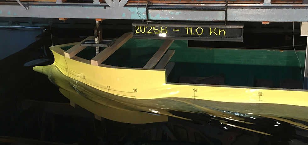
Model tests of the hull form in the tank to this day are the most accurate method for determining the hydrodynamic characteristics of the hull. Despite the automation of model making on CNC machines, this is a long, laborious and costly process. Resistance to the movement of the vessel in the water, optimal screw performance, body behaviour on the wave, consideration of wind load, optimal positioning of the bilge keels, and much other information can be obtained after conducting model tests.
At the same time, methods of numerical modeling of the behavior of a hull in water are constantly being improved and, perhaps, after some time, they will completely replace model tests. Progress in the field of numerical methods for modelling the ship's behaviour in water depends on the use of more powerful processors and more memory for more accurate calculations. A strong impetus in the use of numerical methods was given by the development of cloud computing. A large number of specialized cloud computing centres on the market made it possible to make this service more affordable, and the prices are reasonable not only for large design offices but also for small companies. Now, to get a result, it takes an average of 1-2 days of calculations. You can always speed up the computational process by connecting to the calculation of new processors.

Certainly, the accuracy of the presentation of numerical simulation of the flow around a hull depends not only on the computer power used but also on taking into account all aspects of the flow around a computational mathematical model. The correct setting of a mathematical model requires not only knowledge of the physical nature of the process being modelled, but also some preliminary research to establish the values of the parameters that most accurately describe the model. Independently carry out such calculations can only afford a large company. Most of the design offices use the services of specialized CFD computing firms.
Summarizing the above, we can determine the following conditions for using the results of computer calculations in the design process:
- the results of the calculations may not coincide with the results of model tests, but visually (the representation of the wave surface and the position of the current lines around the body) coincide quite accurately.
- Improving the results of calculations will certainly improve the results of the flow around a real vessel.
- the shape of the wave surface, the location of the streamlines and the distribution of pressures around the hull are credible and are the initial data in the optimization process.
- the accuracy of the calculation very much depends on the accuracy of the representation of the ship’s hull surface. The calculations are carried out on a fine tessellation of the computational grids, and any surface defect can significantly change the flow pattern of the body.
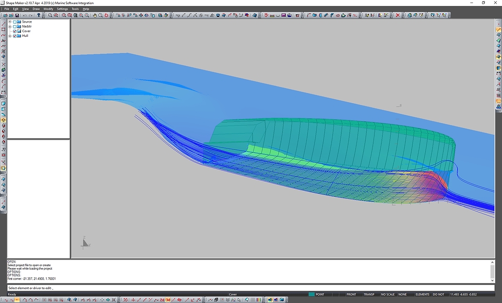
In my opinion, the results of computer calculations are much more informative compared to the results of model tests. For example, the colour visualization of the dynamic pressure component is very informative for the study of flow. Streamlines are also more informative. The ability to calculate several different surface options in a fairly short time also provides undeniable advantages compared to optimizing the hull in the experimental tank.
In fact, the optimization of the surface of the vessel on a computer is practically no different from the optimization in the tank. According to the test results, changes are made to the shape of the body and the tests are repeated once more. The only difference is that it is much easier and faster to change a computer model than a real case used for model tests in a tank. The calculation also does not require a large time and financial costs compared to running the model in the pool and processing the results.

Shape Maker currently has no hydrodynamics calculation module. To perform such calculations, the surface model is transmitted to the hydrodynamics calculation systems. In this case, as a rule, no additional processing of the model is required. The results of the calculations can be loaded into the Shape Maker as a guide for the subsequent reshaping of the surface. Currently, the results of calculations performed in Open FOAM and Fine Marine Numeca Inc. can be loaded into the Shaper Maker. This allows you to significantly speed up the process of changing the shape of the surface for the new iteration.
Of course, surface optimization requires some knowledge and experience in this area. But at the same time, it is possible to achieve quite good results. So, for displacement vessels with a Froude number of 0.2-0.3, the wave component of the resistance can be up to 50% and higher. Therefore, the correct selection of the shape of the fore bulb and the fore ship as a whole can give again in resistance of the order of 10-15%.
The shape of the aft ship also makes a significant contribution to resistance. The shape of the stern is also important to ensure a wake distribution. This significantly enhances the propulsive qualities of the propulsion unit.
As a rule, after receiving the results of calculations on the hull, areas of positive and negative dynamic pressure components are distinguished. In the region of positive pressure, the top of the wave arises, in the region of negative pressure - the bottom of the wave. These areas also affect the direction of the streamlines. The task is to minimize the extremes of pressure and, accordingly, reduce the wave formation.
Ideally, the stream lines should evenly wrap around the body, not clinging to it in the areas of positive pressure and not coming off in the area of negative values of the dynamic pressure component. This is achieved by a local change in the shape of the surface. So, if there is an area of local flattening on the surface — for example, in the area where the frames are stuck to a flat side, an area of negative pressure occurs. In this region, a deeper base of the wave is formed, which passes into the higher apex of the wave in the region of the flat side. This increases the water resistance and negatively affects the flow around the aft ship. It looks as if the ship is rowing a wave by the shoulder. Such a wave can be compensated for by better smoothing the surface shape in the area, as well as by creating a compensating wave with the bulb. The distribution of pressures on the body, as it were, shows us our mistakes made in the design and smoothing of the body.


Comments